Welcome to Dongguan Xinhe Electromechanical!



- All
- Product Management
- News
- Introduction
- Corporate Outlets
- FAQ
- Corporate Video
- Corporate Brochure
News
News center
Contact Us
Headquarter Address: Baihao Industrial Zone, Houjie Town, Dongguan City, Guangdong Province
Tel:+86 769-85923778 85923738
85878200
Fax:+86769-85924507
Website:http://www.dg-xinghe.com
E-mail:cds@dg-xinghe.com
Introduction to the corrector
Published Time:
2012-10-30
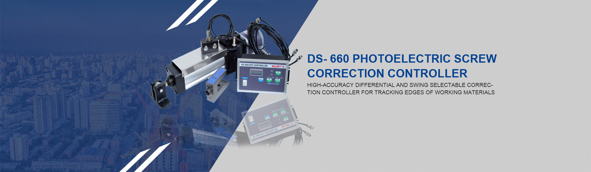
Dongguan Xinhe Electromechanical specializes in the production of edge guiding machines, gasoline-powered edge guiding machines, correcting machines, photoelectric correcting machines, ultrasonic correcting devices, magnetic powder clutches, magnetic powder brakes, air expanding shafts, and other transmission components for packaging and printing machinery. I. Brief Description of Correcting Machine: 1. Brief Description of Correcting Machine: The correcting machine is a device used for correcting the material in heat sealing and cutting bagging machines and printing machine roll materials; the correcting machine is based on the signal transmitted by the photoelectric sensor to the correcting controller, and then the controller outputs a correcting signal to the correcting machine stepper motor, and the stepper motor drives the bottom screw of the machine to move according to the control signal, thereby achieving the correcting effect! II. Classification of Correcting Machines: (1) According to the correcting method
Dongguan Xinhe Electromechanical Specialized in the production of edge guiding machines, gasoline-powered edge guiding machines, correcting machines, photoelectric correcting machines, ultrasonic correcting devices, magnetic powder clutch manufacturers, magnetic powder brake manufacturers, air expanding shafts, and other transmission components for packaging and printing machinery.
I. Brief Description of the Correcting Machine:
1, Correcting Machine Brief Description: The correcting machine is a device used for correcting the deviation of materials in heat sealing and cutting bagging machines and printing machine roll materials; Correcting Machine It works by receiving signals from the photoelectric sensor, which are then transmitted to the correcting controller. The controller outputs correcting signals to the correcting machine's stepper motor. The stepper motor moves the machine's bottom screw rod according to the control signal, thus achieving the correction effect!
II. Classification of Correcting Machines:
(A) Classification by Correction Method:
1. Ordinary Correcting Machine 2. Magnetic Powder Tension Correcting Machine
3. Tension Correcting Machine 4. Magnetic Powder Correcting Machine
5. Single-Channel Correcting Machine 5. Dual-Channel Correcting Machine
(B) Classification by Correcting Machine Specifications:
1. Twenty-inch Correcting Machine Actual Material Passage: 50cm
2. Thirty-inch Correcting Machine Actual Material Passage: 80cm
3. Forty-inch Correcting Machine Actual Material Passage: 100cm
III. Structure of the Correcting Machine:
(A) Overall Structure and Components:
1. Correcting Controller - Tension Controller - Stepper Motor - Magnetic Powder Brake - Photoelectric Sensor - Frame.
(B) System Structure and Composition:
1. Correcting Control System - Power System - Photoelectric Sensor System - Frame System
IV. Working Principle of the Correcting Machine:
Photoelectric Sensor Detection Device --------- Transmits Deviation Data ------》 Correcting Control Device ------- Processes and Outputs Correction Data -------》 Stepper Motor ------- Receives Data and Executes Correction Amount --------- Screw Rod ------》 Completes Correction.
V. Correcting Machine Operation Guide:
1. Step 1: Secure the roll material that needs correction to the specified location on the correcting machine according to the requirements, and connect it to the bagging machine or printing machine as required.
2. Step 2: Connect the correcting machine power cord to the three-phase power socket, turn on the correcting machine controller power switch and photoelectric sensor switch, and check if the correcting controller panel and photoelectric sensor light are displayed normally.
3. Adjust according to the actual correction requirements Photoelectric sensor position 、 Left and right correction buttons 、 Correction speed 、 Tension Single/dual correction adjustment to Single-channel correction 。
4. Correcting controller speed range: 0~10; the smaller the value, the faster the correction speed. It is generally recommended to set the correction speed to 3。
5. Tension controller: It is recommended to adjust to 0.25KG。
6. Adjustment of left and right correction: According to the actual correction needs; correction to the left is set to Left ; correction to the right is set to Right 。
7. Note: Before adjusting any button on the correcting controller, please press the Switch Button 。
VI. Daily Maintenance and Common Faults of the Correcting Machine:
(A) Daily Maintenance of the Correcting Machine:
Before operating the correcting machine:
1. Carefully check if the power switch and correcting control system indicator lights are normal.
2. Check if the photoelectric sensor indicator light is normal and the coordination sensitivity between the photoelectric sensor and the motor.
3. Check if the magnetic powder brake can brake promptly.
4. Add lubricating oil (recommended: engine oil) to the gear contact points to maintain lubrication between the gears, reduce mechanical wear, and ensure correction accuracy.
During operation of the correcting machine:
1. Observe if there are any abnormalities in the indicator lights on the correcting control system panel.
2. Check if there are any abnormalities in the coordination between the photoelectric sensor, the control system, and the motor.
3. Listen for any unusual noises or excessive noise from the mechanical parts.
4. Check if the motor temperature is too high. Generally, around forty degrees is normal.
After operating the correcting machine:
1. Turn off all power to avoid the correcting machine being in standby mode.
2. Close the protective cover of the correcting control device to prevent foreign objects from impacting the control device or damaging the control panel.
3. Add a protective device to the photoelectric sensor to protect it from damage by foreign objects.
4. Add lubricating oil to the motor bearings and screw rods.
5. Add lubricant to the gears and magnetic powder brake.
(B) Common Faults of the Correcting Machine:
1. The signal lights on the correcting machine control system do not display.
2. Slow correction response, overcorrection.
3. Low correction accuracy.
4. The motor does not work.
5. The magnetic powder brake cannot brake promptly.
6. Motor temperature is too high.
Headquarter Address: Baihao Industrial Zone, Houjie Town, Dongguan City, Guangdong Province
Tel:+86769-85923778 85923738 85878200
Fax:+86769-85924507
Website:http://www.dg-xinghe.com
E-mail:cds@dg-xinghe.com
Copyright © 2025 Dongguan Houjie Xinhe Electromechanical Business Department ALL Rights Reserve.